In the top left corner, RX/TX are numbered in correctly, they are really digital 0 and digital 1, not 1 and 2.
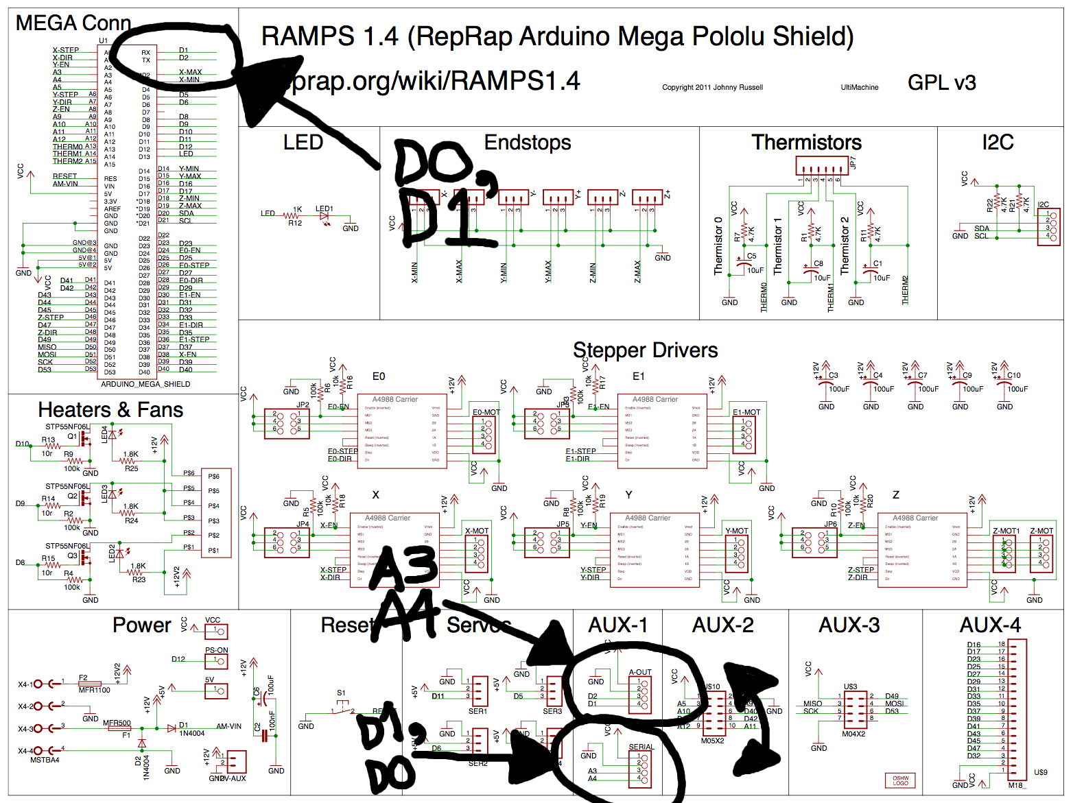
In the middle bottom, A-OUT and SERIAL connectors are basically swapped. SERIAL is really D0, D1 (the RX/TX mentioned above) and not A3, A4. And therefore A-OUT must really be A3, A4.
On the PCB, it's hard to tell which is A-OUT and which is SERIAL on AUX-1. The serial pins have tiny letters "s" next to them. This is the row of 4 towards the center of the board. A-OUT is the row towards the board edge.