It's been a bit of a boring waste of effort sorting out the dogs breakfast to make this work... here's some stuff I did that will hopefully let you not loose time for the same reasons:
a) download the webpack blob, and install it.
b) to get a license, the install dialog didn't send me to their website so i logged in manually and created the free webpack license, downloaded it and then selected it
c) had to install portmap service
d) had to install libstdc++5
e) had to find libmotif3 64-bit deb and install it
floorplanner lauch script is taking forever to load and fail at this point. still trying to sort it out.
f) installed xfonts-100dpi and xfonts-75dpi as recommended in some forum
receiving RPC auth errors on the console,
receiving Wind/U Error (122) Function GetTextMetrics errors on the console
see this other guy's blog post here: http://wienker.org/blog/?p=188 for more issues/solutions
[update] got floorplanner running by following this: http://forums.xilinx.com/t5/Archived-ISE-issues/XPower-in-Linux/td-p/761 where you add some fallback fonts.
portmap rpcbind errors go away if you run rpcbind with "-wi" options instead of default "-w" option, but you'll have to lock yourself down with iptables afterwards.
I'm a sometimes cranky user, developer and admin of Linux since 1993. This blog isn't meant to be some constructive criticism, it's supposed to be a vent hole from which fire gases of displeasure come to the surface. I'll be submitting patches on all this stuff, real soon now.
Friday, May 11, 2012
Sunday, May 6, 2012
RAMPS 1.4 Schematic Errors
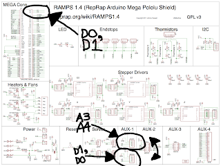
I've been working with the RAMPS 1.4 board design, in particular modifying it a bit and as a result, I've noticed a couple errors...
In the top left corner, RX/TX are numbered in correctly, they are really digital 0 and digital 1, not 1 and 2.
In the middle bottom, A-OUT and SERIAL connectors are basically swapped. SERIAL is really D0, D1 (the RX/TX mentioned above) and not A3, A4. And therefore A-OUT must really be A3, A4.
On the PCB, it's hard to tell which is A-OUT and which is SERIAL on AUX-1. The serial pins have tiny letters "s" next to them. This is the row of 4 towards the center of the board. A-OUT is the row towards the board edge.
Subscribe to:
Comments (Atom)
